|
|
|
To: 6.3 Boundary condition |
As was discussed in section 4.1, in the redistribution
method the diffusion of vorticity is achieved by changing the strengths
![]() of the vortices. Unlike some other methods, the continuous
vorticity field
of the vortices. Unlike some other methods, the continuous
vorticity field
Another place we use the vortex core is when we need to evaluate
pointwise vorticity values for output purposes.
In this case the considerations for the choice of the
most desirable core are somewhat
different. For maximum visual smoothness, a
large core is desirable, since a large core
gives the greatest reduction in short wave errors.
These short wave errors are further also much more pronounced in the vorticity
field than in the velocity evaluation during convection.
On the other hand, there is much less risk that a larger core would
smooth small features, since the actual solution is now known, and
the effect of core size can be determined experimentally without
repeating any of the computation.
Further, even if there would be some loss of information about the shorter
wave lengths in the output for the vorticity,
this loss does not affect the further computation.
Such considerations suggest the use of a second
core different from the one used for convection to do the output.
In fact, there is no good reason why the two cores would need to be the
same. So, for evaluation of the vorticity, we choose a second core
with a high order of accuracy,
since these can be larger for a given accuracy.
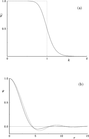
Thus, for the computations of flows in free space in sections
7.1 and 7.2, we choose our
second smoothing function to be a relatively large but
infinite-order core
As shown in section 7.2, the results
are not very sensitive to the precise choice of either of our core shapes.
In most computations in this thesis, as in [201],
a core size ![]() of
of
![]() to
to
![]() was used,
where
was used,
where ![]() is the kinematic viscosity and
is the kinematic viscosity and ![]() is the time step.
is the time step.
Near boundaries, the determination of the pointwise vorticity field runs into difficulties, since the vorticity field beyond the boundary is unknown. In order to compute the correct vorticity near a boundary, the vorticity field must be extrapolated into the boundary in some way.
For our computations of flows around circular cylinders of unit radius in chapter 8, we extrapolated the vorticity into the cylinder by mirroring every vortex into the cylinder to a radial position that is the inverse of the radial position of the original vortex. Further, we changed the strengths of the thus mirrored vortices so that a constant vorticity level outside the cylinder would be extrapolated into a constant vorticity level within the cylinder. It is easily seen that this requires that the strength of each mirrored vortex is reduced by a factor equal to the radial position of the vortex to the power four.
Using this procedure, vorticity fields that are about constant near the wall can be evaluated without difficulty. However, if there are appreciable gradients, they will affect the evaluation of the vorticity. This is evident in our computations of the flow about a cylinder in rotational oscillations in figure 8.2. As expected, our procedure produces a local average of the vorticity near the wall, rather than a pointwise vorticity value at the wall.
To remove such errors would require that the vorticity field is linearly extrapolated into the cylinder, rather than as a constant. This would require some additional coding effort, but does not seem particularly difficult from a fundamental point of view. For a cylinder in steady rotation, figure 8.1 the vorticity flux vanishes at the wall and the error in our simple procedure is much smaller.
One additional modification needed near solid walls concerns the
smoothing function. The smoothing function (6.11)
decays too slowly at large distances to be useful for flows with
solid boundaries; for these flows the vorticity can only be extrapolated
a small distance into the boundary. Instead, for the
flows over circular cylinders in chapter 8
we chose ![]() to be a fourth-order
Gaussian of form [17],
to be a fourth-order
Gaussian of form [17],
 |
A final smoothing function was used to evaluate
the vorticity in three-dimensional flows in free space
in section 7.3.
For two-dimensional flows in free space in
sections 7.1 and 7.2,
Leonard's
infinite order smoothing function (6.12)
above gives excellent results.
In three dimensions, the equivalent infinite order smoothing function is
| (6.15) |
To apply the numerical implementation discussed so far to flows over solid walls we need to address the numerical handling of the boundary condition on solid walls; we will describe that in the next section.