Located in Tallahassee, FL, the ASC advances the science and technology of superconductivity and particularly superconductivity applications. We do this by investigating low temperature and high temperature materials through our research grants and through our collaborations with other universities, national laboratories and industry.

ASC Research Faculty
Florida State University Alumni

Director of ASC
University of Wisconsin-Madison Alumni
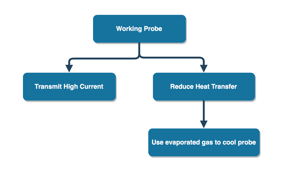
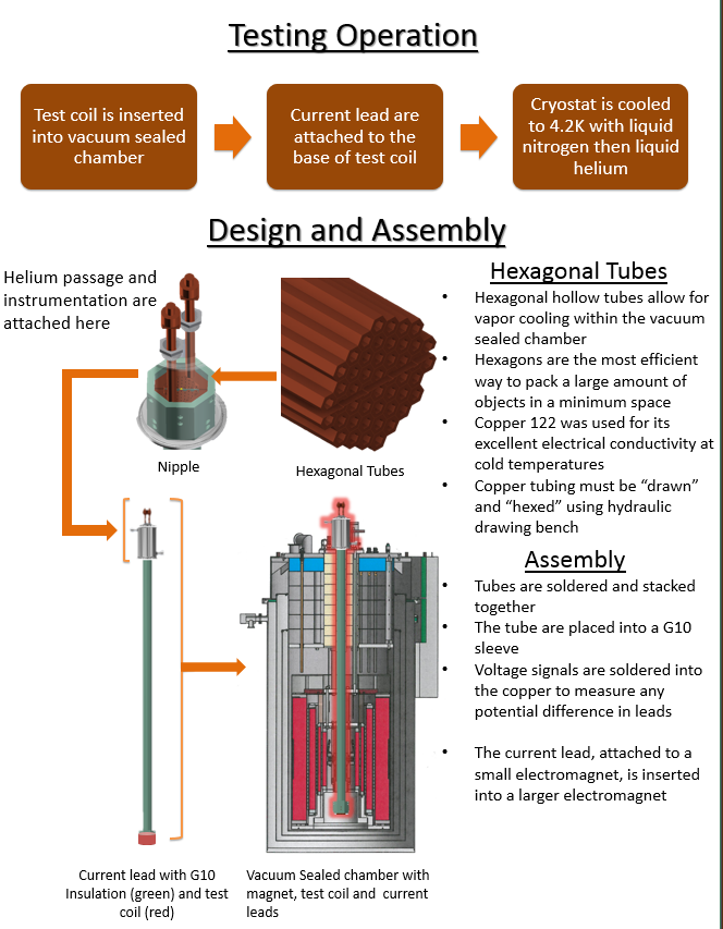
Magnets are used in many applications that use electricity. The machines that use these strong magnets improve quality of living, help save lives, and push the limits of physics research. One machine that uses powerful magnets is the Large Hadron Collider (LHC) used by CERN. In order to create those machines, the magnets need to be tested. Senior design group 501 is assigned the “High Temperature Superconductivity (HTS) Coils” project proposed by sponsor Dr. Ernesto Bosque, with direction from Applied Superconductivity Center (ASC) director Dr. Lance Cooley. The team is working to improve the electrical delivery system to smaller magnets that are inserted into larger outsert magnets. By inserting one magnet into another their fields add to make the magnet stronger. We are designing and improving the current leads that are able to deliver electric current to the smaller magnet. These magnets require a very cold environment to work, which raises two main issues. These issues have to do with the effect of current passing through anything: heat. There are two sources of heat: the first being from the electrical resistance of the material and the second is from the heat of the environment. These heat sources cause the cold fluid to evaporate, curbing magnet performance. To overcome these problems the team is using clever material selection and mechanical configuration. Moreover, the team is using the abundance of resources at its worksite, the ASC. Ultimately the goal is to design a system which will provide 1000 amps losing no more than four watts of heat. This will provide enough electricity through the leads to power the magnet and not waste a lot of cooling resources. This instrument will be a great help to scientists at the ASC working on the future of magnet technology.
What is Superconductivity?
Superconductivity is the ability of certain materials to conduct electric current with practically zero resistance.
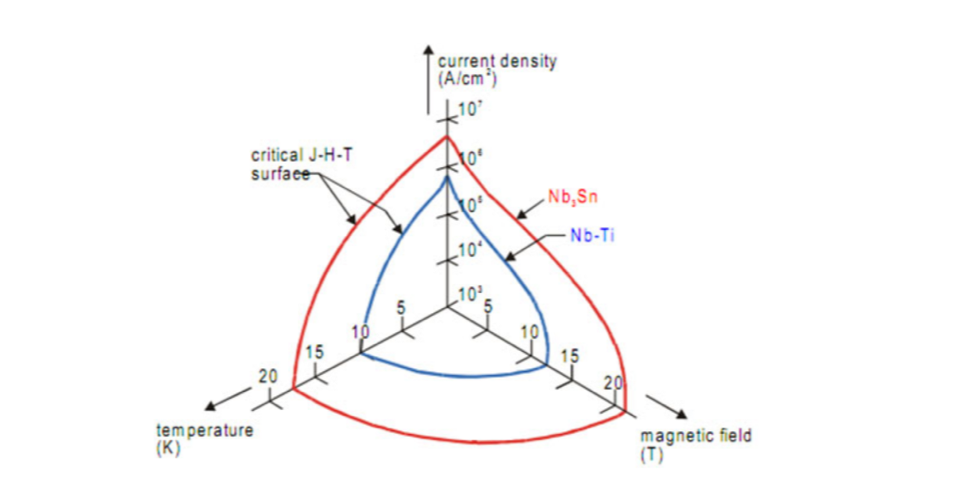
When material such as Niobium Titanium alloy (Nb-Ti), and Nb3Sn are cooled below a transition temperature they become ‘superconducting’
•The superconducting state has zero electrical resistance and high current density
• Selection of cryogenic coolant usually establishes operating temperature
•Superconductive wire can be wound into an electromagnet. High current density results in high magnetic field
•Inserting an electromagnet inside an external magnet can result in extremely high magnetic fields
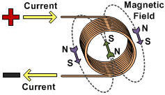
Superconductive wire can be wound into an electromagnet. Inserting an electromagnet inside an external magnet can result in extremely high magnetic fields
The objective of this project is to provide the ASC with a 700A probe for high magnetic field insert coils that will be used in tandem with larger outsert magnets.The minimum objective is to deliver a probe to carry current to the test device with optimization for heat loss
Concepts where classified according to its physical characteristics and properties. These were shaved down by using various techniques including employing house of quality and Pugh charts.
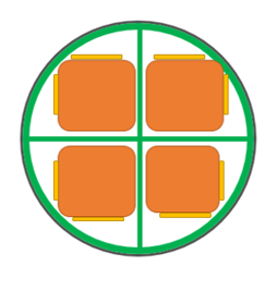
This design incorporates a larger amounts of copper, taking advantage of more tube area and is lined with HTS materials almost the entire length of the current lead. This translated into higher current carrying capability However, calculations showed that the cross-sectional area was still not enough for the desired 1000 amperage.
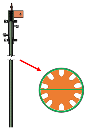
The idea from the previous concept was then stretched to maximize cross-sectional area On top of this, cooling grooves where added to the design to enhance the heat transfer efficiency Producing this design provides a real world challenge and it is very hard to achieve
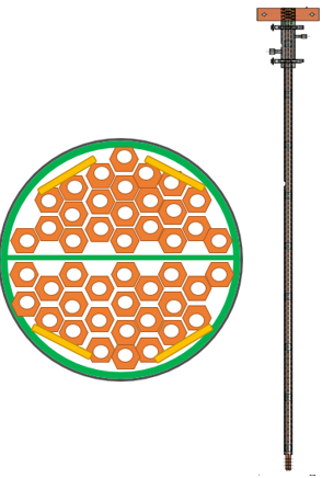
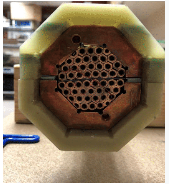
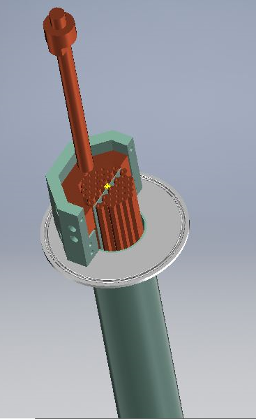
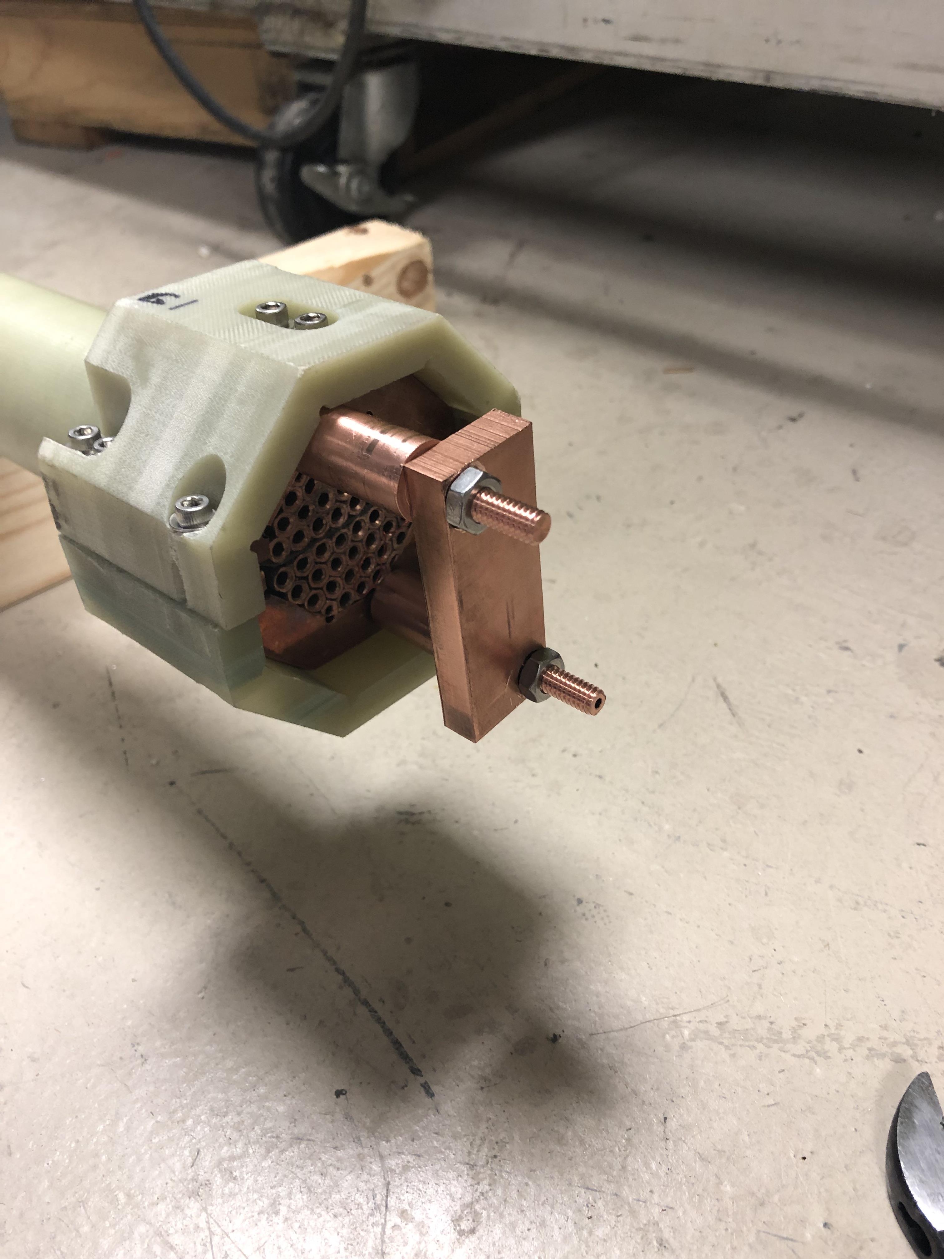
This new design incorporates hundreds of small and readily available copper tubes which will be drawn through a hexagonal dye This shape gives them the ability to have maximal electrical contact while allowing for sufficient evaporated helium gas to pass through the lead. HTS tape runs along the outsides of copper to allow for current sharing
Complex math and heat transfer physics, including utilizing the shape factor and the heat transfer equation was used to find the efficiency of the leads. When the numbers were run for the Standard and Quartered designs and the efficiency could not be brought above 34.40% The Maximized design, while theoretically having an efficiency of 74.17%, was described as being near impossible to machine with the available equipment.The Following design was chosen: Hexagonal Tube Concept
Copper tubing must be “drawn” and “hexed” using a hydraulic drawing bench as shown below
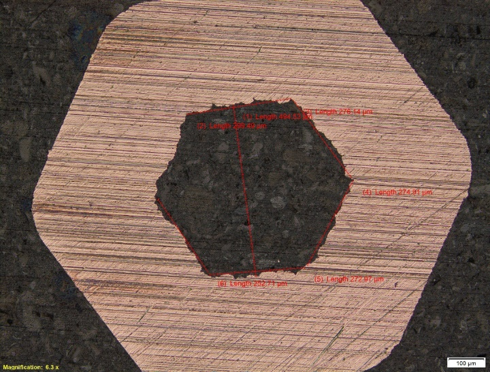
Over 200 tubes will go through this process This shape allows for stacking of the tubes as shown in the embodiment design After stacking, tubes will be set in a resin and placed into the body of the current lead

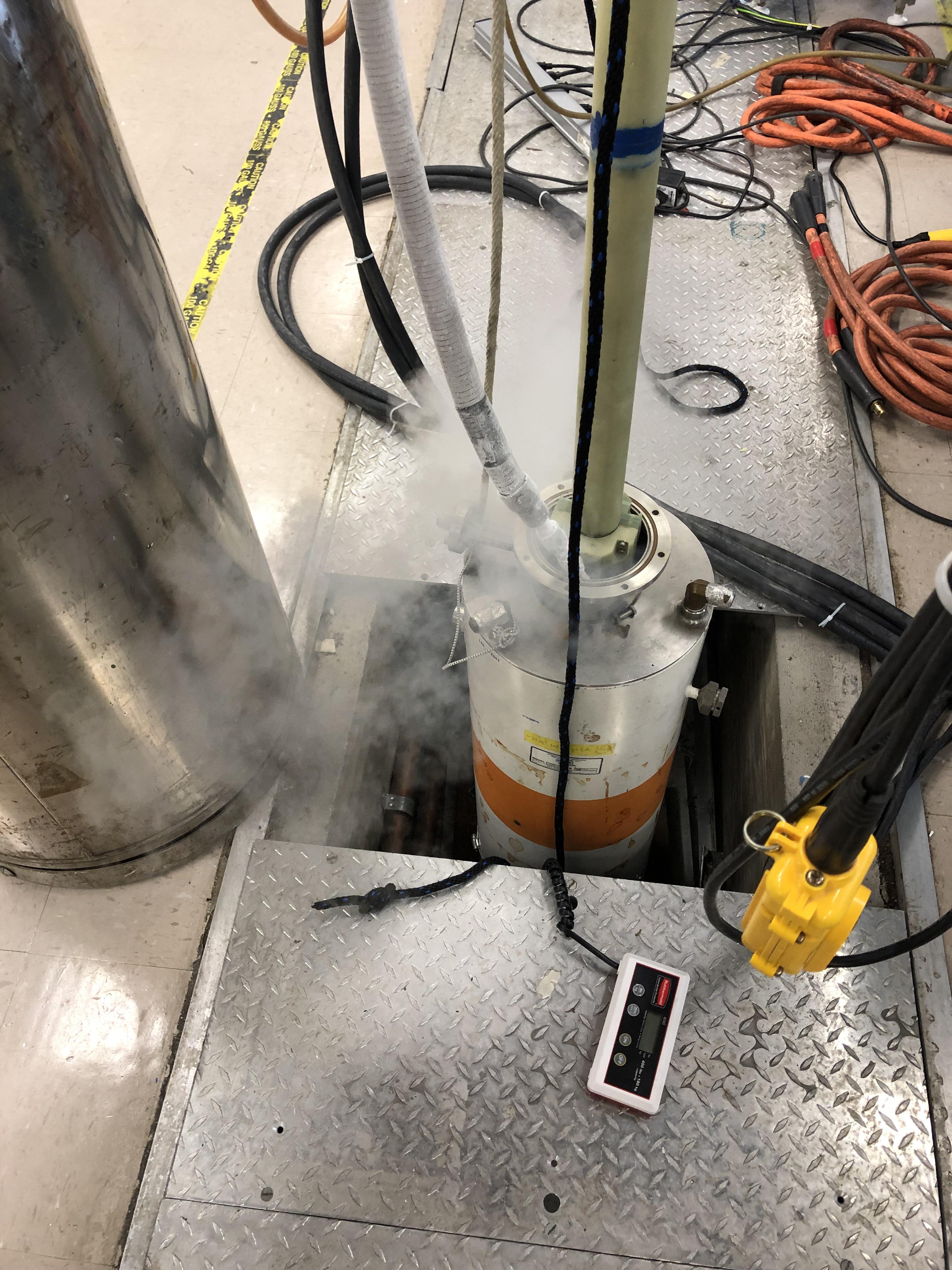
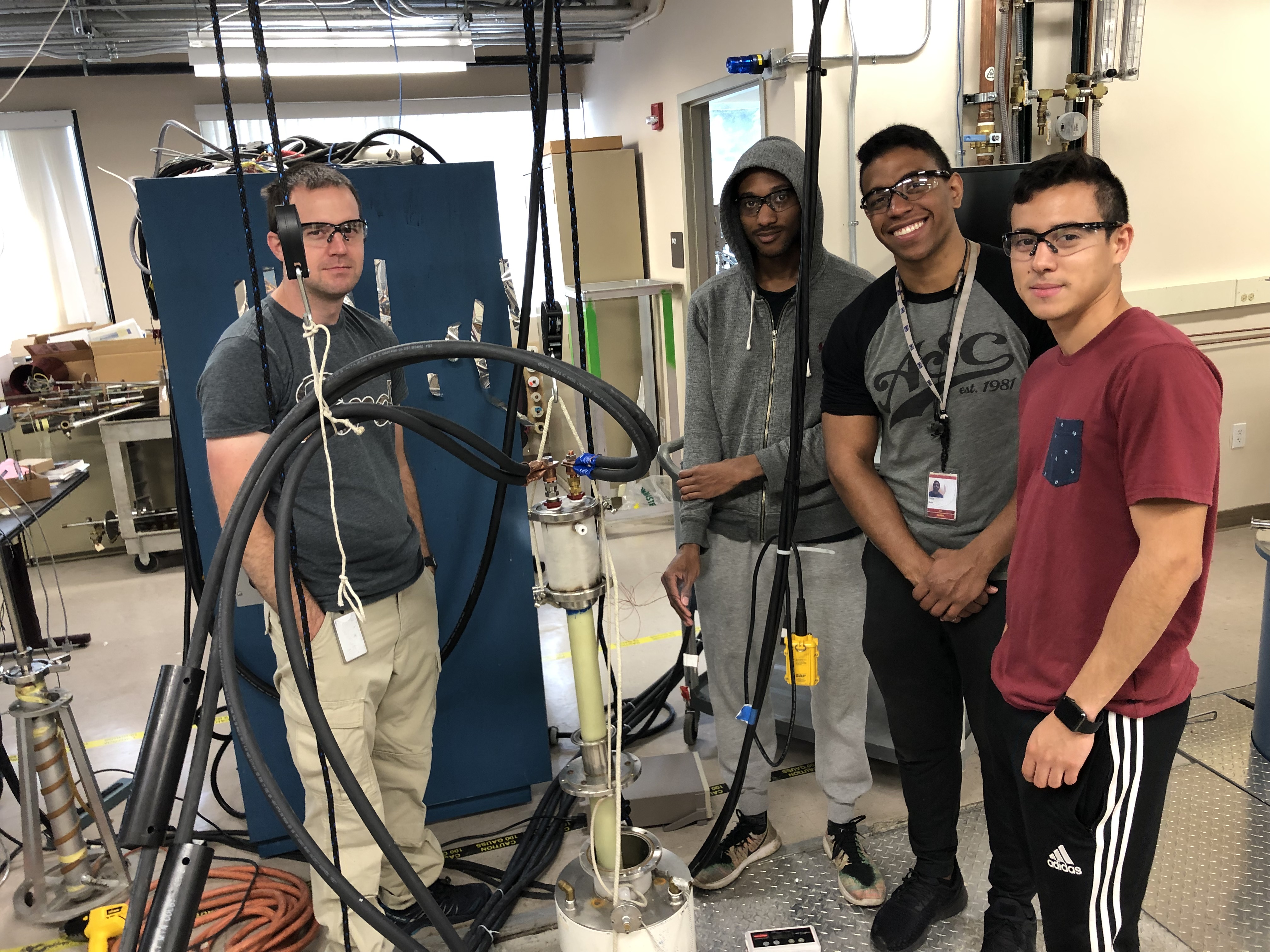
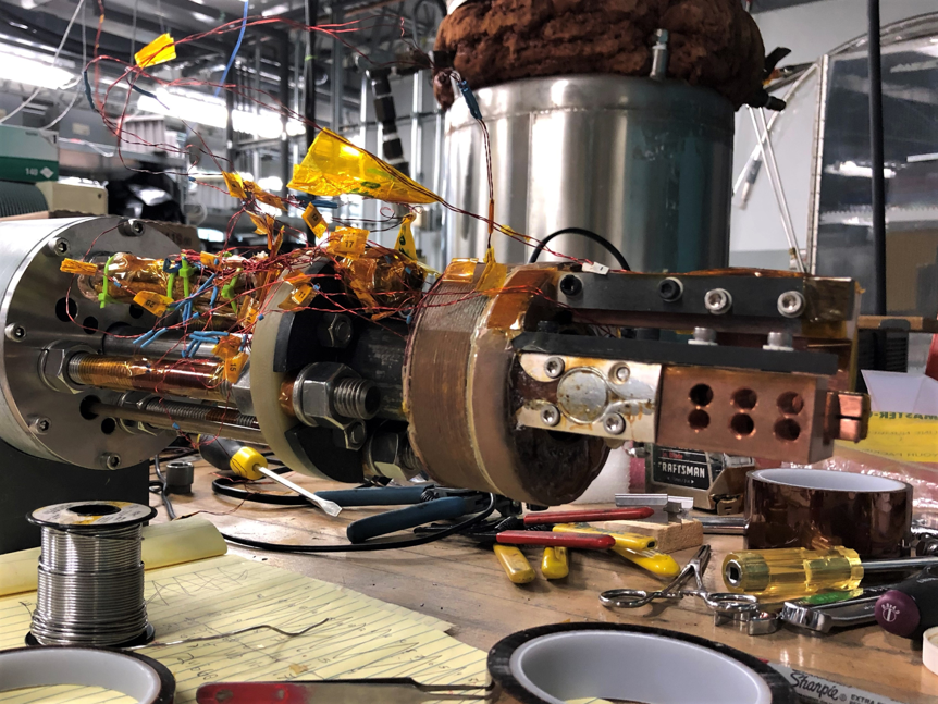
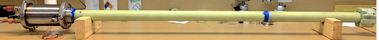
Prototype testing was performed on April 25,2019
The Current lead was submerged in Liquid Nitrogen. Copper was inserted at the bottom of the current lead to create a short circuit and run current through the cooled current lead.
| Metric | Target | Units |
|---|---|---|
| Current Capacity | >700 | Amperes |
| Thermal Dissipation | 4 | Watts |
| Pressure Loss | .5 | PSI |
| Cost | 1,500 | USD |
| Length | 1.75 L 2.5 | Meters |
| Current Lead Shaft Diameter | 50.8 | Millimeters |
| Cross Sectional Area | 2.857 | Centimeter^2 |
| Helium Consumption | 2.875 | Liters/Hour |
| Voltage Drop per Lead | 80 | MilliVolts |
Color Palette