|
|
Quantitative Flow Visualization |
|
|
The main objective of this project is to use the quantitative flow visualization technique into the teaching of thermal and fluids related disciplines by providing visualization-enhanced courseware. This web-based package allows the students to learn many important subjects interactively by using bookmarks and hyperlinkages. The integration of the visualization results and quantitative data provides an optimal way of learning the thermal and fluids subjects because it not only motivates students' interests and enhance their comprehension of the subjects but also stimulates in-depth understanding by allowing full interaction.
"Thermal Sciences" are among the most difficult curricula for undergraduate engineering students. A primary reason is the difficulty in conceptually visualizing thermal/fluid phenomena because most fluids are transparent and their motions and the associated thermal processes are invisible to human eyes. Consequently, visualization methods play an important role in grasping such concepts. In thermal fluid sciences, the understanding of the physical thermal/flow processes can be greatly improved if the flow pattern of interest can be visually observed. In light of this, we produce the following visualization-based courseware as supplement to the teaching of the fluid mechanics. Different from the traditional flow visualization technique, we use a quantitative visualization technique that can not only provide qualitative visualization but also can produce useful velocity and vorticity data. With the aid of this technique, students will be able to directly compared the data to theoretical or numerical results. Whole-field flow measurement and visualization: The Particle Image Velocimetry (PIV) is used to enhance undergraduate laboratory teaching. PIV can provide measurement/visualization of global velocity field information of complex flow fields. Sample projects presented include:
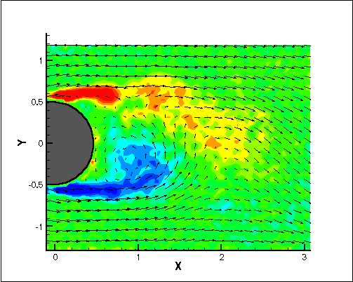
Both the visualization photography and the corresponding whole-field PIV data will be integrated into one database. Useful information of the flow, such as velocity profiles and color-coded vorticity contours, are available on selected regions on the photography using hyperlinks. When the fluid is moving adjacent to a solid surface, its motion depends on the balance of several forces acting upon the fluid particles: frictional force at the surface, viscous force by the neighboring flow stream, and pressure force depending on the external flow condition. The fluid can continue its forward motion if the pressure gradient is favorable. However, if the fluid experiences an adverse pressure gradient, that is when the pressure force is against the motion of the fluid, the fluid particles can be stopped and sometimes be forced to move backward. The retardation and backward-moving motion always occur at the surface since the friction force exerted by the wall is greatest and the fluid momentum is much lower there. When the fluid moves backward at the surface, the following particles have to move away from the surface and the flow is said to be "separated" from the surface. This phenomenon is called "flow separation". When the flow is passing by a bluff body, a strong adverse pressure gradient always presides over the rear half of the body and the flow separates. The flow separation prevents the pressure being recovered in the rear half of the object, therefore, causing a difference in pressure between the front and the back sides of the object. Consequently, a net drag force is acting on the body as is usually called the form drag or pressure drag. In additional to this drag force, the wake flow field is highly unsteady and can induce significant fluctuating lateral loading on the object. The unsteady nature of the wake flow is discussed in more details in the cylinder wake flow web page.
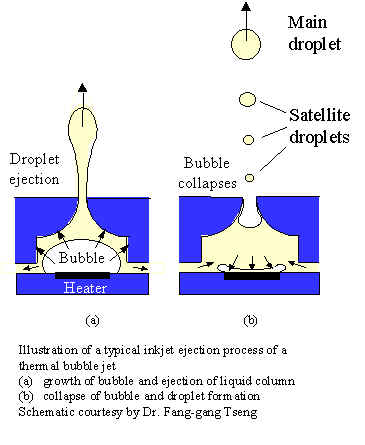
Thermal bubble jet technology has been used widely in commercial inkjet printer. It is one of the most cost-effective ways to produce high quality color printing. Tiny ink droplets are ejected out of the inkjet cartridge to form the print pattern when they impinging on the paper. Inside the inkjet chamber, a thin strip heater vaporizes the liquid ink when an electric current passes through it. The increasing pressure inside the chamber forces the remaining liquid ink to eject out of a nozzle as a liquid jet column. The bubble collapses as the electric current is turned off and the chamber is replenished by liquid ink outside the chamber. This on and off cycle repeats at a very high frequency (~kHz range) and streams of inkjet droplets form the print pattern. This process is illustrated in the following schematic.
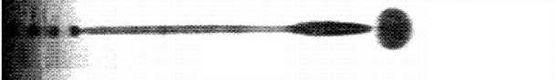
Due to the capillary instability, the ejected jet column breaks up into a primary droplet and a stream of small droplets (satellite droplets) as shown. This ejection process and other interesting subjects related to the inkjet droplet formation can be found in the following web page. · Inkjet Droplet Injection Process
A jet is formed by flow issuing from a nozzle into ambient fluid which can be at rest (a free jet) or moving (a coflowing or counterflowing jet) or tangential to a solid surface (a wall jet). A jet is one of the basic flow configurations which has been widely used in many practical applications such as the fuel injection, combustor, jet engine propulsion exhaust and others. One of the most important considerations for jet flow is the entrainment and mixing process of a jet with respect to its surroundings. For example, in a fuel injector, more uniform mixing and fuel distribution means higher combustion efficiency and better engine performance. In order to characterize the jet mixing process, a jet flow field measured using the Particle Image Velocimetry (PIV) is presented in the following page.
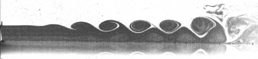
A wall jet is a stream of fluid blown tangentially along a wall and it has a wide range of applications, such as boundary-layer separation control over a wing, film cooling on turbine blades, etc. The photograph shown above is a wall jet flow exiting from a nozzle and the flow is from left to right. Smoke is used to seed the flow in order to visualize the jet and take PIV images. The surface can be seen clearly as the interface line between the jet image and its reflected image from the surface. There are two distinct regions in the wall jet configuration: first, an outer free shear layer that is subjected to the inviscid Kelvin-Helmholtz instability and the formation of large scale vortices; and an inner layer that behaves like a viscous boundary layer. The interaction between large scale structures from the outer layer and inner layer eventually leads to the laminar-to-turbulence transition. This process can be understood better by browsing through the following pages: |