Turbulent Wake FlowBehind a Circular Cylinder |
||||||||||||||||
| Introduction Background PIV technique Particle pathline visualization
|
Figure 1. A sequence of four PIV fields depiciting different developing stages within a vortex shedding cycle. Vortices are shed alternatively from the upper and lower surfaces of the cylinder, creating this periodic flow pattern. Color-code is used to indicate the strength of the flow vorticity. PIV velocity field is represented by the velocity vector data.
External flows past objects have been studied extensively because of their many practical applications. For example, airfoils are made into streamline shapes in order to increase the lifts, and at the same time, reducing the aerodynamic drags exerted on the wings. On the other hand, flow past a blunt body, such as a circular cylinder, usually experiences boundary layer separation and very strong flow oscillations in the wake region behind the body. In certain Reynolds number range, a periodic flow motion will develop in the wake as a result of boundary layer vortice being shed alternatively from either side of the cylinder. This regular pattern of vortices in the wake is called a Karman vortex street. It creates an oscillating flow at a discrete frequency that is correlated to the Reynolds number of the flow. The periodic nature of the vortex shedding phenomenon can sometimes lead to unwanted structural vibrations, especially when the shedding frequency matches one of the resonant frequencies of the structure. One example is the famous Tacoma Narrow bridge incident and this topic has been discussed in great details in the Tacoma bridge link. In this presentation, we are going to investigate the flow past a circular cylinder and study the turbulent wake flow field using the Particle Image Velocimetry (PIV) technique. Based on the PIV velocity field measurements and other reference information, a comprehensive discussion about many important flow concepts such as: boundary layer flow separation, wake flow, vortex shedding, vortex-induced oscillations, aerodynamic loading, momentum balance, and the lift and drag forces on an immerse body, will be given in the following section.
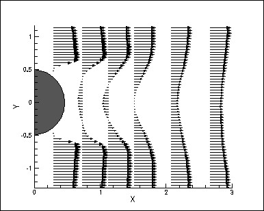
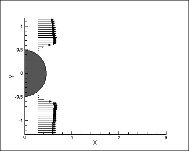
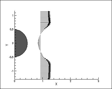
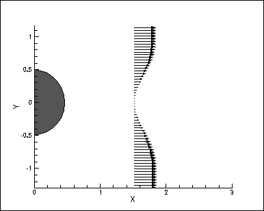
Flow Separation: The presence of the fluid viscosity slows down the fluid particles very close to the solid surface and forms a thin slow-moving fluid layer called a boundary layer. The flow velocity is zero at the surface to satisfy the no-slip boundary condition. Inside the boundary layer, flow momentum is quite low since it experiences a strong viscous flow resistance. Therefore, the boundary layer flow is sensitive to the external pressure gradient (as the form of a pressure force acting upon fluid particles). If the pressure decreses in the direction of the flow, the pressure gradient is said to be favorable. In this case, the pressure force can assist the fluid movement and there is no flow retardation. However, if the pressure is increasing in the direction of the flow, an adverse pressure gradient condition as so it is called exist. In addition to the presence of a strong viscous force, the fluid particles now have to move against the increasing pressure force. Therefore, the fluid particles could be stopped or reversed, causing the neighboring particles to move away from the surface. This phenomenon is called the boundary layer separation. Wake: Consider a fluid particle flows within the boundary layer around the circular cylinder. From the pressure distribution measured in an earlier experiment, the pressure is a maximum at the stagnation point and gradually decreases along the front half of the cylinder. The flow stays attached in this favorable pressure region as expected. However, the pressure starts to increase in the rear half of the cylinder and the particle now experiences an adverse pressure gradient. Consequently, the flow separates from the surface and creating a highly turbulent region behind the cylinder called the wake. The pressure inside the wake region remains low as the flow separates and a net pressure force (pressure drag) is produced. Vortex Shedding: The boundary layer separates from the surface forms a free shear layer and is highly unstable. This shear layer will eventually roll into a discrete vortex and detach from the surface (a phenomenon called vortex shedding). Another type of flow instability emerges as the shear layer vortices shed from both the top and bottom surfaces interact with one another. They shed alternatively from the cylinder and generates a regular vortex pattern (the Karaman vortex street) in the wake (figure 1). The vortex shedding occurs at a discrete frequency and is a function of the Reynolds number. The dimensionless frequency of the vortex shedding, the shedding Strouhal number, St = f D/V, is approximately equal to 0.21 when the Reynolds number is greater than 1,000. Vortex-Induced Vibrations: When vortices shed from the cylinder, uneven pressure distribution develops between the upper and lower surfaces of the cylinder, generating an oscillatory aerodynamic loading (lift) on the cylinder. This unsteady force can induce significant vibrations on a structure, especially if the "resonance" condition is met. The most famous example is the collapse of Tacoma Narrow bridge in 1940 under the action of wind-induced vibrations. It is believed that natural vortex shedding frequency behind the bridge matches one of the resonant modes of the bridge and eventually lead to a catastrophic vibration that destroys the bridge. Please refer to the other links section for a more comprehensive account of the incident. Aerodynamic Loading: According to the Newton's second law, time rate change of the linear momentum is equal to the sum of all external forces acting on a system. Therefore, an integration of the linear momentum inside a control voulme surrounding the circular cylinder can provide information of the aerodynamic forces (lift and drag) acting on the cylinder. As shown in figure 1, and animated PIV vortex shedding sequence, and particle pathline visualization sequence, there are alternative upward and downward flows in the wake as the result of vortex shedding. Consequently, there must be also an oscillatory up and down force acting periodically on the cylinder. This periodic forcing exerting on the cylinder body is responsible for the vortex-induced vibrations as described earlier. Momentum Balance: As stated earlier, the external force acting on an object can be determined using the momentum balance concept. In general, there is a momentum deficit in the wake profile along the streamwise direction as relative to the incoming momentum upstream of the object. Therefore, a simple balance of the momentum flow in and out of the control volume surrounding the object suggests that there is net force acting on the object. (note: the pressure is considered to be relatively constant if the momentum flow is measured far away from the object.) This net force along the flow direction is called the drag. Averaged velocity profiles of the flow past a circular cylinder is provided as a general representation of the wake flow field. Selected profiles at several representative regions is also presented for your reference. Near the cylinder, flow separates from the surface. Immediately behind the cylinder, a recirculation region exists with a strong reversing flow. The region between the cylinder and the end of the recirculation region is called the vortex formation region. The centerline velocity becomes zero at the end of the vortex formation region. Further downstream, the two separating shear layers merge and the velocity profile presents a typical wake profile. It is clear that there is a deficit in the center of the wake. This deficit in the momentum flow is the direct result of drag force acting on the cylinder.
The PIV is a quantitative flow visualization technique, which can be used to determine the instantaneous whole-field fluid velocities by recording and processing the multiply-exposed particle image pattern of small traces suspended in the fluid. The PIV particle image is first obtained by illuminating the seeded flow field with a thin laser sheet. The light scattered by the seed particles generates a particle image pattern. This pattern is recorded using a digital CCD video technique (see figure 2). The local fluid velocity is then obtained using digital signal processing techniques.
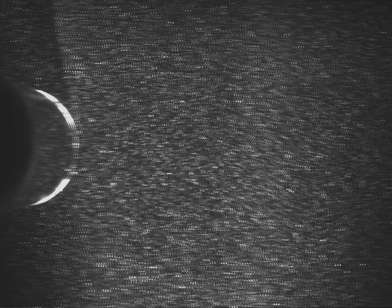
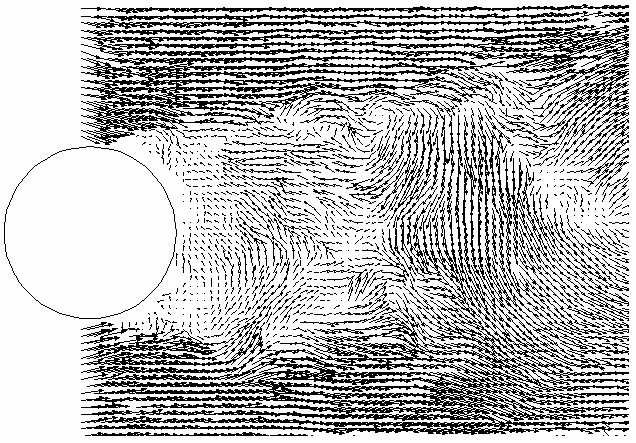
Figure 2. Schematic arrangement of the PIV system Figure 3 is a sample PIV image pattern of the flow past a circular cylinder. The multiple illumination is provided using a rotating multi-faceted mirror. A total of four images are recorded for each particle in successive instants. Fast Fourier Transform (FFT) algorithm and autocorrelation scheme are used to determine the separation between particle pairs. The whole-field velocity vectors can be determined by time differentiation and the result is shown in figure 3. Figure 3 Multiply-exposed PIV particle image field of the flow past a circular cylinder
Figure 4 Corresponding PIV velocity vector field
CCD (Charge-couple device) technology has been used commonly for digital video recording for many years. A CCD imager consists of an array of sensing elements, called pixels, connected to a set of Metal-Oxide Semiconductor (MOS) Capacitors. When a CCD sensor receives light, each pixel absorbed photons and generates electric charge to be stored into the MOS capacitor. The sensitivity of a CCD depends on the capacity (potential well) of the amount of charge it can hold. These charges will need to be transferred to attached electrodes and be amplified to convert into digital signal before the pixels can be exposed to another "picture". Full frame transfer is more sensitive since all sensing array is light sensitive. However, it is usually much slower and not suitable for PIV measurement. Interline transfer mode allows the charges to be moved from the MOS capacitors to neighboring masked area which serves as a buffer area between the readout elements and the photosensing elements. Continuous image acquisition at video rate (30 frame/sec) is therefore possible. One added advantage of this mode is that it enabes the double exposure mode, which allows two consecutive images to be recorded within a very short time period (in the order of msec.) This feature is important for the PIV system as being described in the PIV section.
|
|||||||||||||||
