Analysis and Selection
Analysis
For each concept embodied by using the morph chart, an analysis must be performed in order to choose one concept. This analysis can be done in a variety of manners. One such way is by using a CAD tool, such as ProE in this case, to carefully analyze the concepts. From this analysis, the results obtained will be used to choose the best concept.
Example
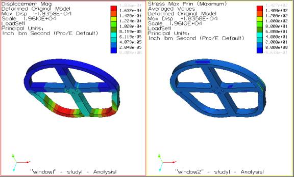
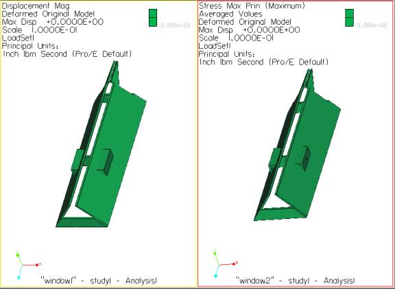
Displacement and Stress analysis at point load on wheels of
100lbs/each. Data confirms
stability of component.
Displacement and Stress analysis at point load on chassis of 400lbs. Data confirms stability of component.
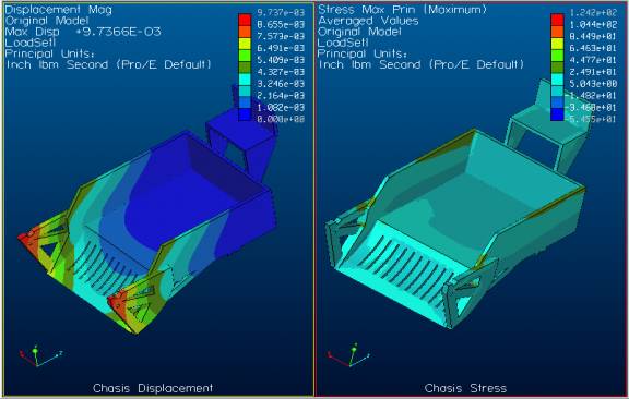
Chassis stress and displacement.
Displacement and Stress analysis at point load on wheels of 100lbs/each. Data confirms stability of component.
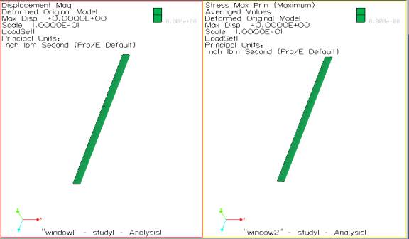
Stress and displacement of a blade.
Analysis for Concept 2
The conveyor is driven via a friction belt located between the rear axle gear. The belt is arranged in a figure eight to allow the rotation induced upon the belt by the rear axle to be reversed so that the conveyor can travel in the correct direction, towards the back of the machine.
The chassis is designed using a single piece of wood. The front axle nubs are located from it as well as openings in the bottom of the chassis to allow the soil on rocks to fall back to the earth. The main portion of the plow is also made from the chassis, but is replaceable if damaged severely. The attachments to which the horses are fastened to are also made from the chassis. All of the wooden pieces are composed of Red Oak, the Young’s modulus has a value of 1.8*10^-6 ldf/in^2 and a density of 6.2162*10^-6 slugs/in^2.
In order to determine if this design is done correctly the pieces of the machine were analyzed using Mechnica. The results of the major components are in the following figures.
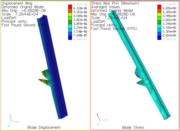
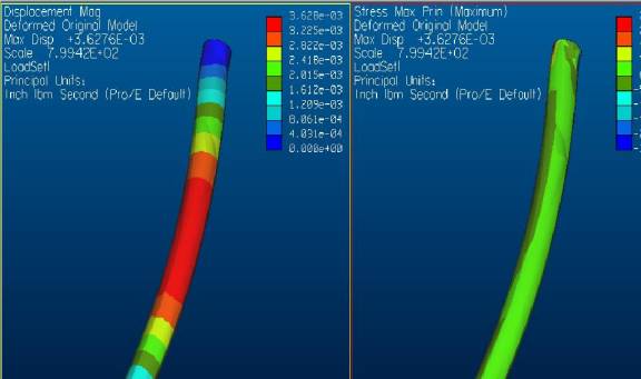
Stress and displacement of steel blade.
This is an example of the steel blade that is placed in front of the plow. The load was added directly to the edge of the blade. The above figure shows stress and displacement. The figures below show the loads placed on the chassis and the displacement and stresses cause by these loads, 9’x6’.
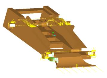
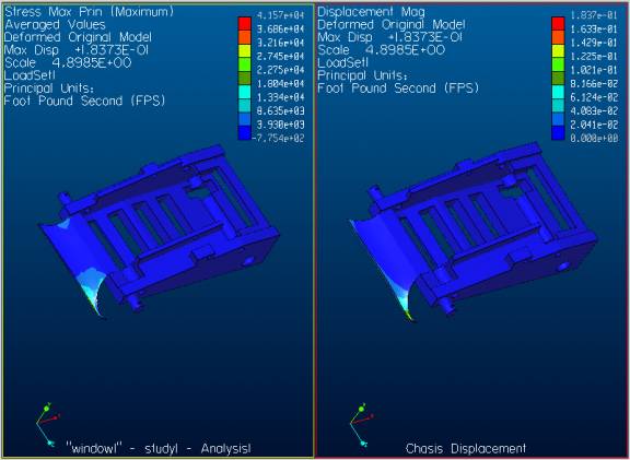
Stress and displacement of chassis.
The following two figures show the load and stress and displacement of the rear shaft, 7’x8”.
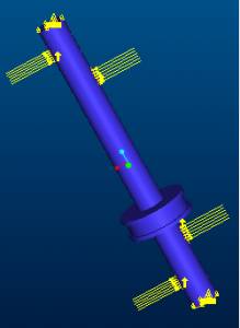
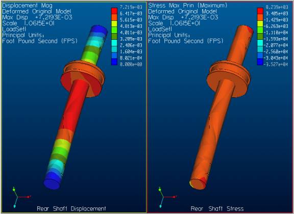
Stress and displacement of the rear shaft.
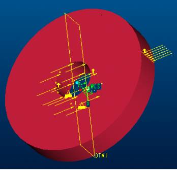
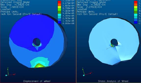
The next figures show the large wheel load and displacement/stress, 3’x6”.
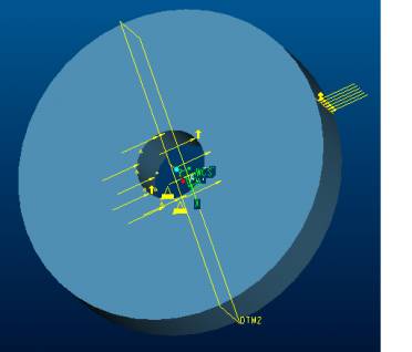
Load placement on the large wheel.
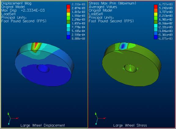
Stress and displacement of the large wheel.
The next figures show the loads and stress/displacement of the small wheel, 2’x 4”.
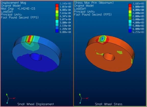
Displacement and stress on the small wheel.
The parts were loaded in the following fashion; the large wheels, shaft and plow were all loaded 500 lb vertically, the plow front edge and blade were loaded with a 500 lb horizontal force. The small wheel was loaded with 200 lb vertical force.
The main reason why this option was not chosen was partly due to the fact that the plow edges would rip of because of the applied force. Another problem is that the vegetables have to travel too high up the plow and the conveyor would not touch the vegetables.
The good attributes are that there are no catastrophic failures and it looks cool.
Analysis for Concept 3
Rear Axle Deflection and Stress
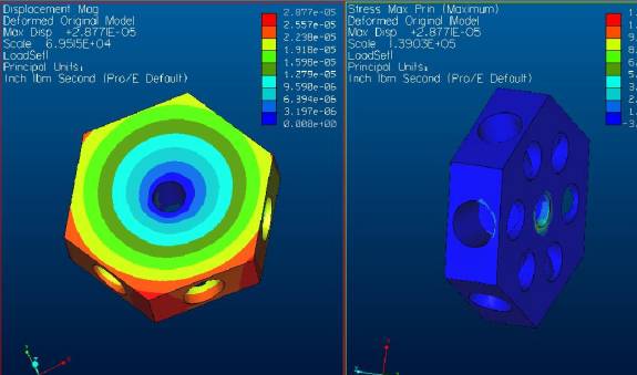
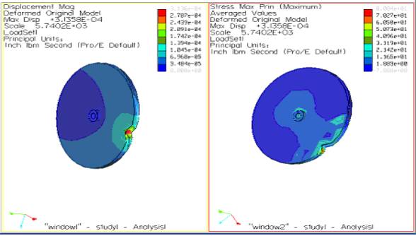
Hexagon Displacement and Stress.
Wheels Displacement and Stress.
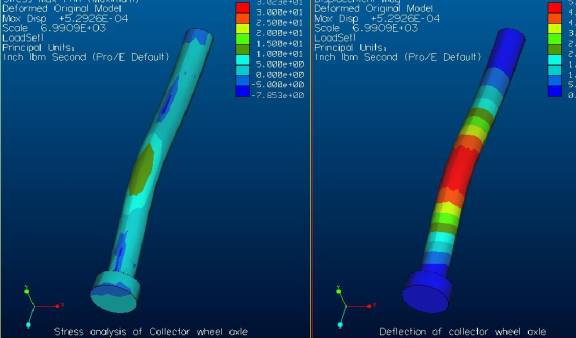
Collector Hexagon Axle Deflection and Displacement.
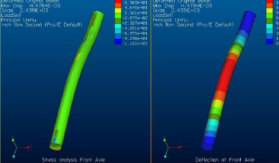
Front Axle Deflection and Displacement.
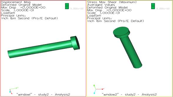
Concept 4
Stress and displacement of wheel.
Displacement and Stress analysis at point load on pins of 100lbs/each. Data confirms stability of component.
Stress and displacement of support bracket.
Displacement and Stress analysis at point load on support brackets of 100lbs/each and 200lbs/each for the two plows. Data confirms stability of component.

Selection
The concept selection is a direct consequence of the concept analysis. By using the technical analysis results, the best concept can be chosen.
Example
Based on the previous analysis, a concept is chosen. This concept is concept 1.