Team 402
Project.
3.D Printed Fiber Optics.
Telecommunication technologies are always changing in regard to data rates and delivery methods. One of these technologies is fiber optics. These cables offer faster delivery rates, better performance over long distances, and reduced weight. NASA has adopted this technology and seeks to improve the way that it is made. The common fiber optic goes through a long and expensive production process, involving chemicals and automation. The answer to replacing this method is to use 3D printing. 3D printing allows fibers to be printed anywhere in the world (or space) and reduces the overall production cost. Current fiber optics use delicate, pure glass while clear 3D printed plastics are an inexpensive substitute. This project will use different types of plastics to try to reproduce the same results with a 3D printed cable, when compared to an industry standard cable. Once completed, NASA will be able to cut down on production and delivery cost while advancing current technologies. Our goal is to create a 3D printed optical fiber that can deliver data over a short distance without major data loss when compared to current cables. By achieving the main goal, we will confirm the concept of 3D printing fiber optics and provide NASA with a solid base for future research.
The primary objective of this project is to create a straight line, functional 3D printed fiber optic. To complete this goal, Camila Arias, Carlos Cuevas, Royce Pokela, Renato Tradardi,and Noah Steighner will be working at the High-Performance and Materials Institute (HPMI) with the help of advisors. To optimize the development of this project, the team will follow Six Sigma’s DMADV (Define, Measure, Analyze, Design, and Verify) approach. This is one of the two six sigma methodologies used to make new manufacturing processes more efficient.
The objective was to outline the business case and understand the requirements of the sponsor. Some of the results for the project are shown below. The Analytical Hierarchy Process, Neutral Density Filters, and Design of Experiments with Results, click on them for a description!
Analytical Hierarchy Process
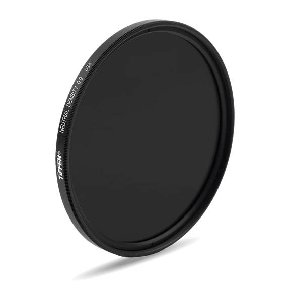
Neutral Density Filter
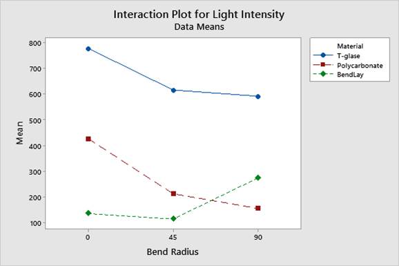
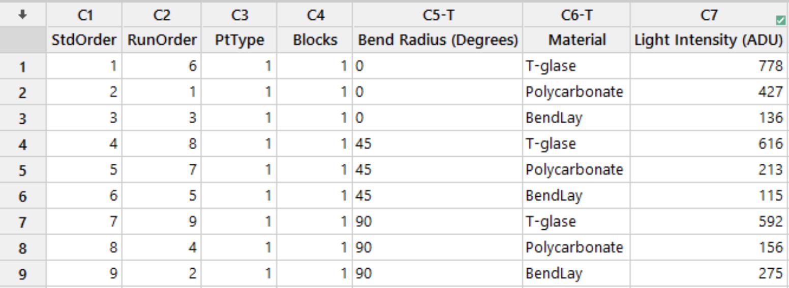
DOE Results
Design of Experiments
Plan.
Define , Measure, Analyze, Design, Verify Methodology!
Some points about our project:
The Define Phase focused on refining the project scope and determining what the bare necessities for completion are. Respectfully, this project should be seen as a success if the team can provide a strong proof of concept that a plastic filament can be used in place of traditional fiber optics throughout 20 centimeters. Once this was established, the team focused on material selection and working on a timeline that the project should be completed by.
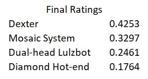
During the Define Phase, six major tasks need to be completed. The first major task is defining customer requirements. This requires a preliminary meeting among team members to discuss the project overview and generate a list of questions for an upcoming meeting with the sponsor of the project. A video-conference meeting allows for face-to-face communication to receive answers to the gathered questions. This task is essential because the project cannot be completed correctly without first defining what the parameters for completion are. From the notes taken from the respective video conference, a list of the bare minimum requirements was written and therefore a list of goals and objectives to meet in succession of one another was created. The second major task is writing the team contract. The team contract is written collaboratively by all group members at once to ensure complete agreement on the terms of the project. The contract is necessary to outline expectations for each member and allow the group to hold each other accountable throughout the project. In a multi-disciplinary project, all group members must be on the same page and have a clear outline for requirements and responsibilities. The third is preliminary material selection. During this task, background research is conducted into 3D printable polymers, traditional fiber optics, polymer fiber optics, and 3-D printing processes. In this process, a list was created of all of the clear, 3-D printable polymers available for purchase. The material properties of each material were researched and evaluated. Based on the sponsor’s requirements, the list was narrowed down to three preliminary materials. The three materials will be tested in later phases to determine which one performs the best. This task is necessary because each material has its printing requirements and behaviors. Each material may melt at a different temperature or adhere to the printing bed differently. These factors must be considered when discussing printing methods and setups. When setting up a test plan, the number of test materials must be known. Also, when setting up a budget, it is important to have an idea of the number of different materials needed, as well as the cost of those materials. The fourth major task is examining the available printing processes. There are five printing processes available, an SLA printer, dual head LulzBot printer, Dexter ® collaborative printers, Diamond hot end printer, and Mosaic printer system. Each printing method has pros and cons, which will need to be evaluated based on the goals of the project. A decision matrix will be created for an objective selection process. This task is necessary because different printing methods provide varying results in structure, size, print speed, finish, etc. To provide the best-printed product, the correct material and printing process must be chosen. The fifth major task is 3D printing training. Every member of the group must know how to 3D print objects by themselves if needed. They must know the process of creating a 3-D CAD model, importing into slicing software, manipulating the g-code associated with the way the printer lays the material and executing a print. 3-D printing training includes a training session with an HPMI researcher, as well as supervised practice prints. Each member will practice printing with basic materials like ABS and PLA before moving on to the more complex optical materials. This is necessary because, in addition to understanding the process, different aspects of the printing filament need to be inspected. This includes temperature, shrinkage, and adhesion to the print bed. All of those aspects and more are important to evaluate before actually printing, and can cause a print to fail if not set accordingly. The final task for the Define Phase is the Define Phase Report. In this report, the project will be introduced, and all objectives, requirements, expectations, and processes will be defined. Each team member will contribute to different areas of the report and should not have an issue with presenting the material when necessary.
The Measure Phase is all about getting testing and getting results. The team had to determine a strong method of testing the concept, eventually falling into the ORCA Flash CMOS Camera. This camera, paired with a Nikon lens and a few 3-D printed structures will allow the team to establish a consistent test - bench to test the respective filaments. The measurement of choice will be light intensity, measured in candela per square meter. See the Material Selection section for more details on selected filaments.
There are five major tasks for the measure phase. The first task is to set up the selected printing processes. This task requires the group to make sure that the SLA printer, the dual head LulzBot printer, Dexter ® collaborative printers, Diamond hot end printer, and Mosaic printer system are all ready to print. The dual-head LulzBot for instance, maybe down and need repairs. SLA printers are required to be cleaned out periodically and a fresh cartridge of filament must be added before a new set of prints is made. The Dexter ® printers require periodic maintenance. This task is necessary so that mechanical problems do not hold the group back in the future. It is important that all printing methods are up and running at the same time and that the group is aware of potential issues for it and know how to fix them. The second major task is to build an optical testing setup. This requires the use of an optical flash camera. The camera will need to be mounted to a fixed position on a workbench and need to be able to be coupled with the prints so that testing can be consistent. This is necessary so that testing can begin and measurements can be obtained. All measurements must be consistent for quality analysis in the following phase. The third major task is to create a baseline control model and obtain the first set of measurements. This will be done using the SLA printer. Due to the higher resolution that it has, it can print a small prototype of an ideal plastic optical fiber. This baseline print will be tested with the optical testing setup to obtain a preliminary set of measurements. Using these measurements, it would be possible to obtain a better idea of the performance expectations of future FDM prints. The fourth major task is to create CAD models and g-codes for test prints based on preliminary measurements. With the test data from the baseline model in mind, CAD models will be created for FDM printed prototypes. These prototypes will be compared to the baseline model after being printed. Before printed, the CAD models must be imported into a 3D slicing software to create g-codes for the printers. These g-codes are very important because they determine the internal structure of the print. It is necessary to do this to have a set of files ready to create all of the needed test prints for the next phase. The fifth major task is purchasing all the materials needed for prints in the next phase. This task can be done at any time throughout the phase but must be completed before the phase is over so that all purchased materials are available at the beginning of the following semester.
There are three major tasks for the analyze phase. The first major task is to create all of the new prints with the newly ordered materials. Using the g-codes from the following phase and the printer setups, new prints can immediately be made at the beginning of the phase. These prints will all be used to gather data for the final analysis before creating the final design. The second major task is to obtain all measurement data and compile it for comparison. This requires the group to use the optical flash camera to measure the light transmission through each print. The prints will be between three separate materials, different bend angles, different internal structures, and they will be printed on different machines. All of this data will need to be gathered and compiled for comparison, most likely in MATLAB. After gathering the data, it was be analyzed for decision making. This is necessary for the final report so that all of the decisions made are backed by data and the best material and print structure is used in the final designs. The third major task is the analyze report, where all of the data will be analyzed and interpreted for integration in the design phase. The group will write this report following the data analysis and include all conclusions and decisions made ahead of the design phase
In the design phase, the team researched light filters that would help give desired results, deciding on a neutral density filter. When coupled with the laser, the light intensity still proved to be high to obtain accurate values. For this reason, the laser was replaced with an LED flashlight and a re-design of the testing setup was done. This included new holders for the fibers, input light source, and camera to make an easier testing setup, leading to obtaining accurate results.
Once results deemed accurate, a design of experiments (DOE) was completed that included testing each material three times at three different angles. Different cuts of the filament were used each time to ensure consistency. Finally, results were analyzed and drawn into visual tools such as graphs. Conclusions were made in respect to a preferred filament, choosing Bendlay to embed in our prototype, leading into the verify phase. In the verify phase, a prototype was constructed that would embed multiple fibers at different angles. These angles included 0, 45, and 90 degrees. Theoretically, each of these fibers could be individually tested and would prove that it was possible to embed a fiber within a printed structure, achieving the customer’s final requirement for the project. Using a dual-headed extruder for the LulzBot TAZ 6, the team attempted to print this embedded structure. After a few days of troubleshooting this printer, the team was then asked to wrap up the project, prior to a successful print. This was due to external reasons, namely the COVID-19 pandemic. Despite this, the team continued to work on analytics and research, being able to successfully conclude the project with a CAD design of the final prototype and finished analysis.
Material Selection.
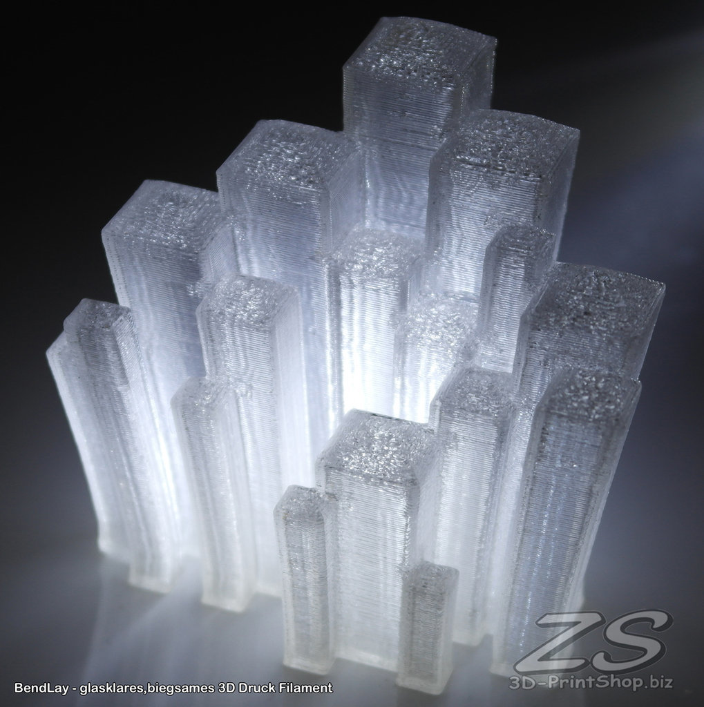
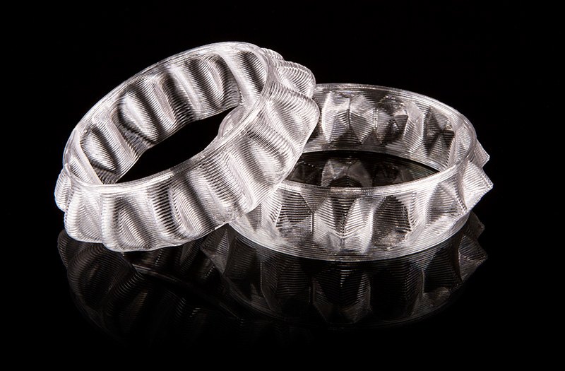
BendLay
T-Glase
Polycarbonate
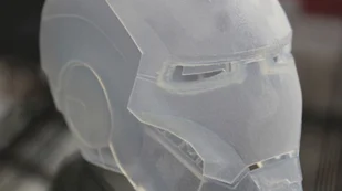
Optically Pure.
Is what the team had to focus on when selecting a material. Arguably, the material selection process was the most important for the project. Without an optically pure filament, the proof of concept could never have been established. Similarly, if the filament is not easily accessible at a reasonable price, then the project would be pointless. The main characteristics the team was searching for ways to be as close to pure glass as possible, while still having the ability to 3-D print.
Our top three materials: T-Glase, BendLay, and Polycarbonate.
T-Glase. The number one filament in our design, showcasing a multitude of attractive features. T-Glase needs to be printed between 235 - 240 degrees Celcius for optimum printing. This filament is Food and Drug Administration approved and tested to be 100% reclaimable. Per industry standard, T-Glase is considered colorless or "water clear". While unprinted it remains clear, several changes need to be made to the slicer program to ensure it remains that way. Increase the nozzle thickness to a minimum of 70%, layer thickness to 70% of nozzle size, and slow the speed of the print. With these three things, we can guarantee the optical pureness of T-Glase.
Polycarbonate. One of the most well-known materials for its' strength, toughness, and optical transparencies. Cheap and readily available, this filament is worth looking at. Optimal temperatures are between 290 and 315 degrees Celsius, noticeably higher than the other filaments.
BendLay. A filament known for its strength and flexibility, while also being semi-transparent ( allowing no less than 90% of light transmitted through it). BendLay needs to be printed between 215 - 240 degrees Celsius. Being just as clear as Polycarbonate, BendLay offers lesswater absorption and no whitening when bending. For all practical purposes, BendLay is a close third in our materials selection.
T-Glase was chosen as the best filament. Due to the manufacturing process, the team accredits the better transmission to the higher reflectivity and transparency. T-Glase was chosen to embed in the final prototype.
Our team was thoughtfully chosen , click to find out more about each member!:

Camila Arias
Industrial Engineer.
Verify Phase Leader.

Carlos Cuevas
Electrical Engineer.
Design Phase Leader.

Noah Steighner
Computer Engineer.
Measure Phase Leader.

Renato Tradardi
Mechanical Engineer.
Analyze Phase Leader.
Royce Pokela
Mechanical Engineer.
Define Phase Leader.
Progression.
Track Our Progression Through the Phases Here! Currently on Measure Phase, with Define completed!
- Define
- Team Assignment
- Team Contract
- Preliminary Research
- Materials Selection
- Printer Process Selection
-
8 weeks
Aug. 26th - Oct 20th
- Measure
- Printer Setup and Configuration
- Optical Testing Build
- Baseline Control Model
- CAD Designs and G-Mode Manipulation
- Purchasing
-
7 weeks
Oct. 21st - Dec. 6th
- Analyze
- Professional Camera Training
- Newly Printed Materials
- Measurement of Data
- Processing of Data
- Analysis of Data
-
4 weeks
Jan. 7th - Feb. 4th
- Design
- Switched to LED input light source
- Added neutral density filters
- Redesigned fiber holders at 0, 45, and 90 degrees
- Obtained baseline measurements
- Performed Design of Experiments
-
4 weeks
Feb 5th - March 4th
- Verify
- Created CAD Model of Initial Prototype
- Troubleshot Dual Headed LulzBot
- 3D Printed two material designs
- Completed design day report and presentation
- Prepared business analysis report
-
6 weeks
March 4th - April 16th
Contact.
Have Any Questions Concerning Our Research or Progress? Contact a team member directly or send us a message!