Top-level description:
This design incorporated the use of Invar and symmetry as often as possible to ensure minimum displacement from the designed focal point of the lens. This was accomplished by using plates for the lateral orientation mounting the optical fiber. Since the focal length of the lenses has less tolerance restrictions than the lateral positioning, all clamping forces are aligned in this direction. Additionally the lateral adjusting mechanisms are disengaged after alignment to prevent influencing the position as the thermal conditions change.
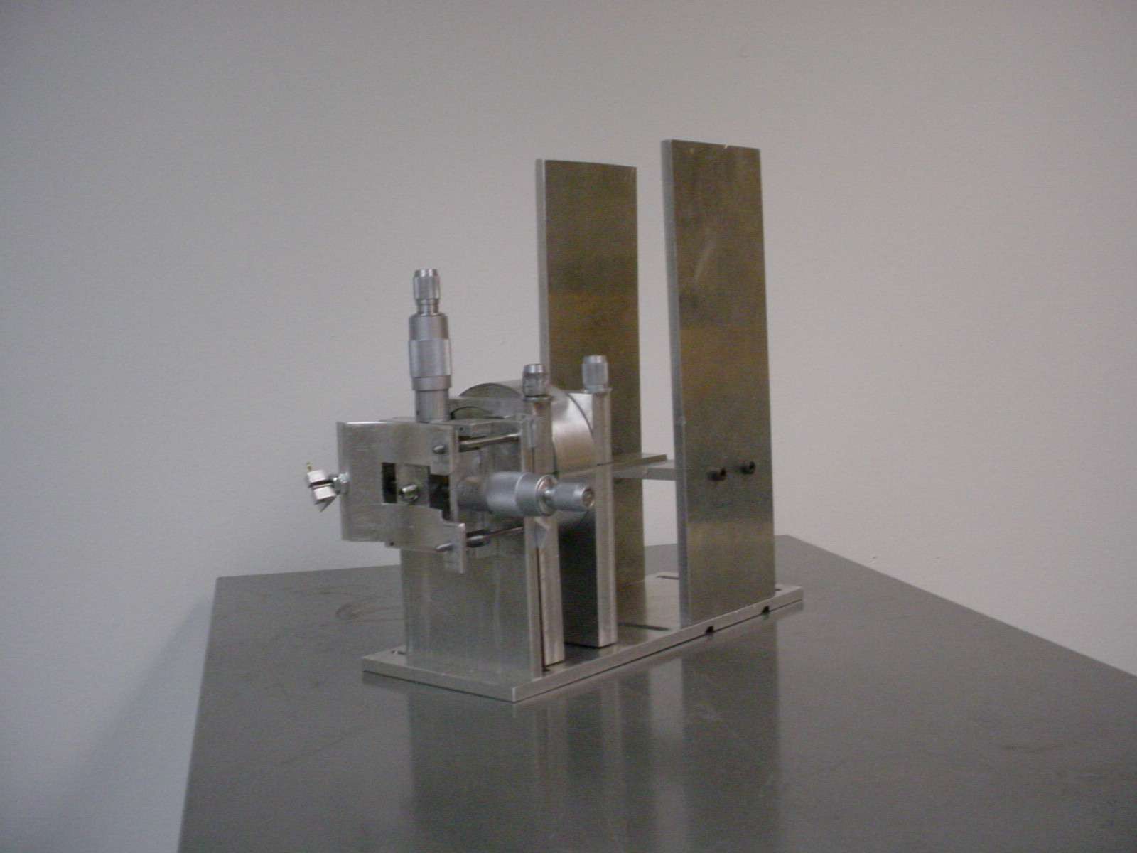
Figure 11: Final Design
Specific feature description:
The following description utilizes a horizontal position of the adjustment assembly. All references to up, down, vertical, and horizontal in the following description assumes this orientation even though this might not be the orientation as installed. The overall system requires two adjustment assemblies mounted at a right angle to the splitter housing and base plate. The splitter housing and base plate have no moving parts and are described as unit separately from the adjustment assemblies.
Adjustment Assemblies
The lateral adjustment is achieved by turning the two micrometer screws. Each screw indexes the fiber optical pickup in a perpendicular direction.
Figure 2: Final Lateral Adjustment Assembly

Once the desired position is reached, the assembly is locked down to prevent further movement.
Figure 3: Spring Locking Mechanism

A toggle latch on the face opposite of the upper rail-adjusting knob maintains the spring tension. T-pins inserted into the spring and the lower receiver group maintains tension on the end of the spring oriented towards the adjusting knob on the upper rail group. When the toggle latch is in the release position, the tension on the spring is reduced allowing for easier adjustment of the assemblies in the lateral directions. Once the lateral adjustments are set, the toggle latch is lowered to its locked position. This action increases the tension in the spring and effectively presses the fiber optic mounting plate, upper rail assembly and lower rail assembly tightly together. Lateral alignment of the optical fiber is maintained by friction between these components. When the toggle latch in the locked position, the carriers, adjusting screws, gears and knobs can be effectively removed them from the system, by rotating the micrometer screws in the counterclockwise direction. This action provides thermal isolation of the rail assemblies and fiber optic mounting plate with respect to the adjustment mechanisms.
Longitudinal Adjustment
The longitudinal adjustment mounts the lens inside of a carrier. This carrier is then threaded into an exterior collar. As the exterior collar is rotated, the inside carrier rides back and forth along two aligning pins (see figure 16). Since there are 22 threads per inch between the collar and carrier, adjustment can be made well within the desired tolerance.
Figure 4: Final Longitudinal Adjusting Assembly

Base plate and splitter housing
 The base plate and splitter housing assemblies are not temperature
sensitive and therefore are constructed of aluminum or other readily
available, machinable material. The base plate allows for generic
breadboard mounting to the existing structure of the LADAR system.
The splitter housing consists of a series of plates mounted to the
base plate that provides a platform for the splitter block to rest
upon at the appropriate height. The flanges of the adjusting assemblies
mount to the splitter assembly to both support the adjusting
assemblies and mount the lenses in the proper orientation between
the splitter and the adjusting assemblies.
The base plate and splitter housing assemblies are not temperature
sensitive and therefore are constructed of aluminum or other readily
available, machinable material. The base plate allows for generic
breadboard mounting to the existing structure of the LADAR system.
The splitter housing consists of a series of plates mounted to the
base plate that provides a platform for the splitter block to rest
upon at the appropriate height. The flanges of the adjusting assemblies
mount to the splitter assembly to both support the adjusting
assemblies and mount the lenses in the proper orientation between
the splitter and the adjusting assemblies.
Future Plans
Due to software issues with the College of Engineering, a Finite Element Analysis of the final redesign was unable to be performed at the current time. If the problem is rectified in a timely fashion, then an FEA can be done. In order to truly test the performance of our system the current receiver assembly would have to be removed. This removal would cause the Loral Laser Radar to become uncalibrated, and add an extra week of work to regain calibration. Hence our system has not been tested on the actual Loral Laser Radar. Since amateurs performed the machining of the prototype, the system does not contain the precise adjustments or the thermal considerations that are required for the actual receiver assembly. However, the purpose of the prototype was to give a basic representation of the working model. From this prototype Eglin plans to use all of our Engineering drawings and the Invar that was ordered to construct the actual working receiver assembly that we designed. The system can then be mounted to the breadboard, calibrated and tested for thermal stability and proper alignment.